2005 LANEY VC30-112 GUITAR AMPLIFIER
Repair Log – 2005 Laney VC30-112, 30 Watt ‘class A’ combo 1 by 12 guitar amplifier Serial no JVxxxx.
23/03/17 Copyright reserved Terry Relph-Knight
Value – As is, maybe – £ 300, £480 to 500 (inc postage) new
Description
The Laney VC30 is now a discontinued product. It is Laney’s version of the Vox AC30 configuration. Another model, the VC30-212, featured a larger cabinet with two 12 inch loudspeakers, just like the Vox. The Laney VC30 amplifier also appeared with a flat baffle and an HH loudspeaker, where the large magnet was so close to the valves that the magnetic field interfered with correct operation and caused red plating. Other versions with an HH loudspeaker, but mounted on a sloping recessed front panel, are apparently OK because the magnet is further away from the valves.

REPAIR LOG – 2005 LANEY VC30-112
The Laney VC30-112 combo uses four EL84’s (TAD STR Selected S1’s) with no negative feedback around the power amplifier, running in ‘class A’ to produce 30Watts into a single 12 inch loudspeaker. The amp is fitted with a single Celestion Seventy 80 G12P-80 8ohm loudspeaker. The Laney tech department tell me the amplifier in for repair is 12 years old.
The VC30 has an Accutronics 16 ¾ inch, four spring (a pair of 2 springs in series) reverb tank. The tank output should be oriented at the power switch end of the amplifier to avoid feedback and connected to the red phono on the PCB. The white phono is the drive to the input of the tank. The amp has an FX loop for external effects and an external dual foot switch can be used to switch the reverb on and off and to switch between clean and drive. The Reverb level control runs directly into the power amp input and the reverb is in parallel with the effects loop.
This is a two channel amp with a clean and an over driven channel. Switched to the over driven channel with the Drive and Drive Volume at maximum there seems to be a ridiculous amount of gain and therefore quite a high level of noise from the input valve.
Valve complement – 3 x 12AX7, 4 x EL84, the two pre-amp valves and the four output valves appear original and are TAD brand. The phase splitter has a different appearance and no surviving brand or type markings (the Laney VC30 manual confirms that all three pre-amp valves are ECC83 / 12AX7s, so the phase splitter is not a different dual triode. The first 12AX7 is described as needing to be a ‘high grade’ by which they likely mean low noise, low microphonic’s).
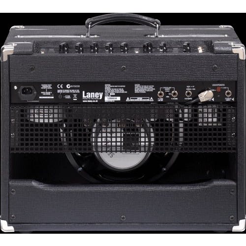
Laney VC30 rear
The EL84s all have retaining clips (the retainers on output valve 2 and 4 have snapped in half) and the 12AX7s have sprung screening cans.
Laney number these valves as V1,V2,V3 (all 12AX7),V4,V5,V6 and V7 (all EL84) from right to left looking at the back of the amplifier.
Front panel controls – Input Lo, Input Hi, Clean Volume, Bright switch, Drive, Drive Volume, Drive switch, Drive LED, Bass, Middle, Treble, Reverb, FX Level (on some versions this was an extra tone control), Standby switch, Power Switch, Power LED. The front panel is mirror polished stainless steel with the control labels silk-screened in black, Unfortunately some of the silk-screening has started to flake away. Personally I do not see how any form of silk-screen printing can be expected to stick to a highly polished metal surface, but Laney say that these panels were printed with a 2 pack epoxy ink and that therefore ‘it is impossible’ for the lettering to just flake off (obviously, they are wrong).
NOTE – The tone control design on this amp is the configuration that passes no signal if all three tone stack control are set fully anti-clockwise.
Back Panel – IEC 3 pin fused mains socket, 20mm HT fuse, Internal ‘cabinet’ (loudspeaker) jack, 8ohm / 4ohm output impedance switch, FX Return jack, FX Send jack and Drive/ Reverb foot-switch jack.
A rather poor feature of the construction of this amplifier is the use of ¼ inch smooth shaft, grub-screw chicken head knobs fitted to 6mm, split shaft, knurled controls. Since the the knobs don’t fit properly they tend to fall off, or spin uselessly.
Another dumb thing, common to all Laney amplifiers, is having the internal loudspeaker cable threaded through one of the square perforations in the rear protective grille. Which means you cannot unscrew the grille and remove it completely, to get it out of the way during repairs, because it remains tethered to the amplifier by the loudspeaker cable. I cut out one side of the perforation so now the grille can easily be removed and replaced.
The original strap handle on the top of this amplifier has been removed and replaced, rather sloppily, with a larger handle. The new handle has been mounted with mismatched screws, off centre and at an angle. Apart from the problem with the handle, the flaking control labelling on the front panel, the burnt out output valves, the broken valve retainers, knobs that don’t fit the control shafts, a 230V power supply that runs HT and heaters way over the maximum specification and the chassis retaining screws that are too short, this amplifier is in very good condition.
Problems – Amplifier crackles after being left on for a while. There is also a lot of hum from the loudspeaker. Two of the EL84 spring retainer clips snapped in half while I was removing the output valves. Carrying handle has been replaced with a poorly mounted, off centre handle, held on with mismatched wood screws. The 6 bolts that hold the amplifier chassis in place aren’t long enough and only barely engage with the cage nuts on the chassis. In fact only 4 bolts can engage with the nuts. As usual with Laney the internal loudspeaker cable is threaded through the rear protective grille because they were too lazy to cut a notch in it.
Just about to ship the amplifier out of the door when I find there is a problem with the heaters not working on the (2nd set off replacements) output valve nearest the mains transformer (blown heater filament connection).
Oh for crying out loud!! Fitted the heater voltage dropping diodes and the four Electro Harmonix EL84s supplied by client and about to declare the repair done when I find that with the Reverb level at around 5 (all other knobs at zero) the reverb tank feeds back at around A 220Hz.
Work done – Replaced the set of four matched TAD EL84 output tubes with a set of four matched JJ low dissipation EL84, Plate current 47.1mA, Transconductance 10. Output valves still red-plated so increased the cathode bias resistor from 56 to 68 ohms. I still had a red plating problem on one of the four valves so I returned the valves to Hot Rox for re-testing. 05/05/17 Received a replacement set of EL84’s PC 38.1, TC 9.7 from Hot Rox. These don’t red plate, however the heaters on one of the JJ EL84 exhibited a bright heater flare where one end of the filament was welded to the pins. After a short period of testing one end of the heater filament disconnected from the weld to the pin in the valve base.
Eventually fitted two pairs of 6amp rated, back-to-back diodes mounted on a tag panel to drop the heater voltage down to something that won’t fry the valve heaters. The TAD EL84 data sheet gives the max and min ratings for the heater voltage as 6.8 to 5.8 volts. The measured heater voltage with the old set of TAD EL84s was 7.88V AC !!
Replaced all EL84s with a matched set of Electro Harmonix supplied by Folkies. Also replaced the first 12AX7 in the pre-amp which was very noisy and crackly.
Hum is much reduced. Replaced the broken valve retainer clips. I removed the poorly mounted handle, measured and drilled holes and refitted the handle with a pair of 5mm bolts. Tightened loose nuts on the two loudspeaker jacks. Added card inserts into the slots in the eight bifurcated control shafts in an attempt to stop the shaft closing up under pressure of the knob grub screws, with the knob loosening or falling off as a result. Cleaned a lot of dirt from the back side of the PCB.
Amplifier wiped clean on the outside and vacuumed inside to remove dust.
Reverb feedback problem – tried reversing the reverb tank in the cabinet. Feedback problem solved, even with the Reverb level at maximum – no feedback.
Oh… and … the six bolts that are supposed to hold the chassis into the cabinet by engaging with cage nuts, are just that little bit too short. You are lucky if you can even get a couple of turns of thread to engage and even then you cannot get all six bolts into all six nuts because the chassis is about 3mm narrower than the cabinet !!!!
I replaced the two bolts on input side of the cabinet with two M5 30mm. DO NOT put these bolts anywhere else they may short out the electronics in other positions.
Rather too many instances of shoddy, thrown together stuff that doesn’t quite fit on this amp if you ask me. Screwed up handle (probably an owner fix, although in that case the original handle likely failed as it was only held on with wood screws), silk screen labels flaking off the front panel, ¼ inch knobs that don’t fit 6mm knurled pot shafts, loudspeaker cable ‘trapped’ in rear mesh, bolts that are supposed to hold the chassis into the cabinet that are too short. Over high voltages from the power supply because the amp is designed for 230V AC and has no adjustment for real UK mains voltage (the power transformer also seems designed for and expectation of lower than 230V so the actual output voltages on real 240V are way over stressing the valves). And a reverb tank fitted the “wrong way round” that tended to feed back.
A note on class ‘A amplifiers’
Most guitar amplifiers with a push-pull output stage operate in class B or class A/B. The Laney VC30, like the Vox AC30, runs the output stage in ‘class A’. This puts a lot of stress on the four output valves because, unlike most guitar amplifiers which idle the output valves at a lower power, the output valves in a class A design are biased to run flat out all the time. It’s a bit of a juggling act to design the output stage so that the valves are operated just at, or just below, their operating maximums. This is not helped by the fact that due to European Union legislation, most modern guitar amplifiers are designed to run on 230V mains. The mains voltage at most places in the UK is still 240V or higher. As a result the HT voltages (and heater voltages) for these valves amps run high. The HT is perhaps 20V higher than they were designed for. When you run a class A amplifier, already designed to run the output valves at close to maximum, with a higher HT voltage you are asking for trouble and heater voltages that exceed the specified maximum will cause the heaters to fail (Laney say otherwise on both counts).
There may also be variations between different valve brands in the degree to which they will withstand operation at or past their maximum ratings. In general, Class A amplifiers are likely to require their output valves be changed more frequently.
Diagnostics
Once the back grille was removed is was clear to see that, after the amplifier has been left on for while, the leftmost two EL84’s (viewed from the back of the amplifier) are red plating, so they are obviously passing too much current. This could mean that either the grid resistors or connections are bad, or that the output transformer has a short (transformer checks out OK). The odd crackling and popping noises are probably due to the overheating valves momentarily shorting internally – (it later turns out the first 12AX7 was in poor shape and making horrible noises).
Output transformer primary is Blue – Black CT – Red. Blue to Black 36.3 ohms, and Red to Black 38.4 ohms. It’s the blue side pair of valves that are red plating which do have the lower resistance half of the winding.
EL84
Pin 1 Internal connection 82ohm to pin 9
Pin 2 Grid 1 1K5 to pin 6
Pin 3 Cathode and Grid 3
Pin 4 Filament
Pin 5 Filament
Pin 6 Internal connection 1K5 from pin 2
Pin 7 Anode
Pin 8 Internal connection – the internal connections on the TAD valves really don’t go anywhere
Pin 9 Grid 2 82ohm from pin 1
NOTE 1 – Laney have used pins 1 and pin 6 as support points for the control and screen grid 1.5K and 82 ohm resistor connections. THIS CAN BE DANGEROUS. These pins are marked as ‘Internal connection’ on many data sheets. Most new production valves have nothing internally connected to these pins. However some valves, particularly NOS, DO HAVE connections, for example Pin 1 is connected to Pin 2, the control grid. Damage will occur if valves that do have internal connections are plugged in to this amplifier.
NOTE 2 – Some versions of this amplifier are fitted with a single HH loudspeaker (with a ‘flat’ baffle, sloping baffle version is OK). The magnet on these sits very close to the output valves. Close enough that the magnetic field from the loudspeaker influences the performance of the valves, causing low output power and early failure. Looking at the back of the amp the EL84 second from the right is the worst affected. Later versions of this amplifier use a Celestion Seventy 80 loudspeaker with a smaller magnet and are apparently not as badly affected (might still be a long term problem?).
According to the circuit diagram, all four output valves are cathode biased at 9V with a common 56ohm 5Watt resistor to ground (measures 10.7V). Combined cathode current at 9V would be 160mA or 40mA per EL84. At 10.7V across the cathode bias resistor, current is 191mA or 47.74mA per valve. In single valve operation, Ia is rated at 48mA.
Why one half of the push pull, red-plates, is a bit of a mystery (as noted previously it may be because these valves are connected to the lower resistance half of the output transformer primary) because all the grid resistors and connections seem to check out. All grid stoppers on pins 1 measure around 1.5K and the common ends of those to ground measure 220K. All suppressor grid (pins 9) resistors measure 82 ohms and are connected to B+. Most likely this set of valves is simply worn out.
Transformer Red is 317.5V (38.4 ohms to the CT) and Blue is 315.5V (36.3 ohms to the CT). Black (B+) is 318.2V.
For convenience I have numbered the output valves from left to right looking at the back of the amplifier as 1,2,3 &4. The spring valve retainers on output valve 2 and 4 have snapped in half.
All four valves have brown spots on the inside of the glass envelope opposite the grid alignment hole in the anode, so it certainly looks like all four have been working hard for some time.
As an experiment I swapped 3 and 4 for 1 and 2 to see if the red plating followed the valves or stayed on the same half of the output transformer primary.
With the valves swapped the red plating follows 3 & 4. 3 & 4 are running about 250 degrees on the glass while (4 is the most visible red) 1 & 2 are at 215 degrees. The red plating is most visible on the side of the amp that faces outwards when mounted in the cabinet.
Unfortunately the amp still red-plates with a brand new set of JJ EL84s.
An LTSpice computer simulation of the output stage shows it performing exactly as the circuit diagram indicates. The voltage drop across the common cathode bias resistor is 9.26V and the total cathode current is 165.5mA.
Measurements with the old set of TAD output valves.
Heaters – 7.74V AC this is very high, nominal is 6.3V
After the addition of the back-to-back diodes the heaters receive 6.36V.
B+ 321V – circuit shows 290V
Suppressor grid common 308.3V – circuit shows 280V
Input grid common for blue pair 4.2V !!!! (it is the blue pair that are obviously red plating)
Input grid common for red pair 0.75V !!!!
Voltage across the cathode bias resistor starts around 10 and then slowly keeps on rising.
The high heater and supply voltages are because this amp is designed for 230V mains and is running on 240V actual UK mains.
The only reason I can see for DC voltages on the common grid drives is that the coupling caps from the phase splitter are leaking. Certainly the LTSpice simulation shows no volts on the grids. The caps in the Laney are dark blue 22nF 630V plastic film. The PCB is printed with 400V for those caps.
Tried disconnecting the 22nF coupling caps C12 and C14.
With the caps disconnected and the back of the PCB cleaned, the pair of EL84’s that drive the blue side of the output transformer still have 1.9 odd volts on the common grid connection where it would normally connect with the phase splitter coupling cap.
With all 4 EL84’s unplugged and power applied there is no voltage on either the common grid connections or across the cathode bias resistor.
With the 4 new JJ EL84s each common grid connection has perhaps 30mV and the cathode bias sees about 10.8V. However this voltage does seem to slowly rise. It does seem as though the old valves are trashed and the voltages apparent on the grids are caused by the bad valves.
However the cathode bias level is high and the valves still red plate. I shall try a 68 ohm cathode bias.
With a 68 ohm cathode resistor the cathode bias is 11.83V
B+ 326V – circuit shows 290V
Suppressor grid common 315.7V – circuit shows 280V
Input grid common for blue pair 30mV
Input grid common for red pair 56mV
Red voltage is 324V
Blue voltage is 323V
Valve temperature is between 220 and 240 degrees.
Red drop 3.01V (38.4 ohms) current = 0.078385417 Amps = 23.932 Watts for the red pair
Blue drop 2.56 (36.3 ohms) current = 0.070523416 Amps = 21.509 Watts for the blue pair
Re-test
Red drop 3.111V (38.4 ohms) current = 0.081015625 Amps @ 311.9V drop across the valves = 25.268 Watts for the red pair (labelled 1 and 2 with silver marker)
Blue drop 2.571V (36.3 ohms) current = 0.070826446 Amps @ 312.3V drop across the valves = 22.119 Watts for the blue pair (labelled 3 and 4 with silver marker)
In an attempt to balanced the power of each pair I swapped 1 with 3.
Red drop 2.708V (38.4 ohms) current = 0.070520833 Amps @ 312.8V drop across the valves = 22.058 Watts for the red pair (labelled 3 and 2 with silver marker)
Blue drop 3.023V (36.3 ohms) current = 0.083278237 Amps @ 313.1V drop across the valves = 26.074 Watts for the blue pair (labelled 1 and 4 with silver marker)
Try 3,4,1,2
Red drop 2.705V (38.4 ohms) current = 0.070442708 Amps @ 307.7V drop across the valves = 21.675 Watts for the red pair (labelled 3 and 4 with silver marker)
Blue drop 2.938V (36.3 ohms) current = 0.080936639 Amps @ 307.5V drop across the valves = 24.88 Watts for the blue pair (labelled 1 and 2 with silver marker)
Re-tested with 230V AC mains set and supplied by Variac.
Even at 230V AC the second EL84 from the mains transformer still red plates. It has to be because the supposed matched set I purchased from Hot Rox just are not balanced.
05/05/17 Received a replacement set of EL84’s PC 38.1, TC 9.7 from Hot Rox.
29/08/17 Replaced output valves with a set of Electro Harmonix EL84s
Valve temperature is around 220 to 190 degrees C.
Output power test
The amplifier develops 40.4 V peak to peak into an 8 ohm resistive load at 400Hz.
That’s 25.5 Watts.
I contacted Laney technical support about the red plating problem and this is what they said –
For the first 13 years of its life the VC30 had a HT of 320V and the were no problems encountered, this is a standard voltage for an amp of this type,
The voltages were lowered slightly due to power surges in Australia, as here the supply voltage is 240V, but their voltage does vary and can be as high as 260V, we had a few instances where the power fuse would blow for no apparent reason.
To rectify this we reduced the voltage and added a surge guard to the power supply, this does however come at a price and the output is reduced slightly below 30W output.
I do not think the transformer is a problem on your amp, but you are more than welcome to purchase a new transformer to try, another thing to check is the output tubes as we have seen matched sets that were very poorly matched.
We can supply a new transformer for £46.99 shipped to a UK address.
Regards
Dave Thompson
UK Service & Production Supervisor
http://www.facebook.com/laneyamplification
Parts – 2 x replacement valve clips £4, 4 x P600A 6A diodes £1.56, tag panel £1.0, spacers £0.50, bolts £2.50, 68ohm 5W wire wound resistor £0.50, JJ 12AX7 £13.00, 2 x Electro Harmonix 12AX7s £ 25.95
Total parts – £ 49.01
Repair Log: 1965 Epiphone Olympic Special (looks like a Gibson Melody Maker) SN:xxxxxx
Copyright reserved T Relph-Knight 19/09/17
Value – £750 to 800? although Reverb lists 1965s of this model @ £916, or in excellent condition (still showing a few chips and dings around the edges of the body and at the headstock) @ £1,453.
The New Kings Road Vintage Guitar Emporium UK listed a 1964 Epiphone Olympic (with a sprung steel Vibrola vibrato) for £1,115 in January of this year.
Weight – 2.7 kg 5.95 lbs
A quite heavily worn, double cutaway, Epiphone Olympic Special. The Olympic Special was introduced in 1962 and discontinued in 1970. The asymmetrical body with the bass horn slightly longer than the treble was introduced in 1965. The guitars serial number does not show a hit on the Epiphone serial number database. GuitarHQ.com states that Gibson made, Epiphone serials, in the range 250336 to 305983 are for 1965. These Olympic Specials were made in the Gibson Kalamazoo plant alongside the Gibson Melody Maker, using the same woods and other materials. At least one of these guitars is in circulation with the ‘Melody Maker’ name in block white letters on the strip of pick guard just below the end of the fret board, although it is possible these might be a pick guard swap from a Gibson guitar or a Gibson spare replacement. It’s likely that these guitars were produced with the Epiphone brand, simply because at the time it allowed Gibson to expand its distribution by running two brands.
Epiphone has used the ‘Olympic’ name for quite a number of models over the years and there may even be some confusion among enthusiasts over which Epiphone’s truly are ‘Olympic’ models. Currently the Olympic name seems to apply to a flat top acoustic Epiphone guitar.
Around 1965, the Olympic was also made with a six on a side batwing headstock and a ‘Crestwood’ / ‘Wilshire’ body shape (a blockier more square body shape with a long upper horn). It seems as though Gibson standardised on the one shape for Epiphone guitars and simply fitted extra pickups, fancier binding / inlays and vibratos to differentiate between the models. This may have been so that none of the Epiphone branded guitars looked quite so much like guitars in the Gibson range, in this case the Melody maker.
Body – This guitar has a one piece mahogany body (1 3/8 inches thick, same as a Gibson SG) in a dark brown to yellow vintage sunburst finish. The thin celluloid, faux tortoise shell, pick guard is attached with seven small, blackened steel, wood screws. The pick guard has shrunken slightly, pulling the screws out of vertical in their holes. The single coil pickup at the bridge has no height adjustment, it is simply bolted to the pick guard. The guitar has 250K log Volume and Tone controls fitted with push on Gibson gold ‘bell’ knobs with the silver anodised metal inserts. The tone capacitor is a disc ceramic.
Neck – 22 jumbo frets on a rosewood fretboard, one piece mahogany, set neck. Some visible fret wear on the first 3 frets under the plain strings. The back of the neck has numerous finish chips and dents. A lot of the finish in missing on the treble side between the nut and the ninth fret. Two of the ¼ inch mother of pearl fret markers (there are markers above the 3, 5, 7, 9, 12, 15, 17, 19 and 21 frets) are missing; one above the third fret and one of the pair above the twelfth fret. Side dots are 1/8 inch white plastic. The narrow headstock is black painted and parallel sided, with an “open book” crest. The Epiphone name is printed in gold along the centre of the headstock.
Fitted with two, three-on-a-strip, Kluson nickel plated, pressed steel tuners with oval white plastic buttons. These are stamped DELUXE on the back of each tuner shell. These are not the original tuners, as marks from six individual tuners appear in the finish, concealed under the 3 on a side strips. Although strip Kluson tuners were used on the Olympic, so the current tuners are correct to the model and may in fact be the third set on this guitar (original strip Klusons changed for individual tuners, then the individual tuners changed for the existing Kluson strips).
A single action truss rod adjusts with a 5/16” hex nut at the headstock, access covered by a large black/white plastic laminate cover, secured by two screws. The neck joins the body at the 18th fret.
The guitar is fitted with a nickel plated wrap around bridge with a “lightning bolt” ridge and two grub screws to angle the bridge at the posts. This is original to the guitar and model. The ‘lightning’ ridge is compensated for a wound third string and in the 1960s the guitar would originally have shipped with a set of 0.012 gauge strings, with a wound third.
Re-strung with Ernie Ball 2215 Nickel Wound Electric Guitar Strings 10-52 Skinny Top Heavy Bottom.
Problems – In for cleaning (the guitar is quite grubby) and a light restoration. Dots at the third fret and twelfth fret are missing and are to be replaced. Straplock buttons to be replaced with ‘normal’ strap buttons. The two bell knobs are quite battered and the tone knob is no longer secure on the pot shaft. A fret rocker test shows frets: 6, 11, 13, 14, 16 and 21 are high.
Work done – Guitar cleaned and polished. High frets hammered and filed down until a fret rocker test shows they are level with the other frets. Fretboard and frets cleaned and polished. Missing dots replaced. New volume and tone knobs. New standard strap buttons fitted in place of the locking buttons. The middle two screws on each strip of 3 tuners were a poor fit and screwed in at an angle. Screw holes plugged and re-drilled.
Replaced the old ‘lightning ridge compensated for a wound third’ wrap over bridge with a Wilkinson adjustable intonation bridge. The volume and tone controls were sprayed with De-Oxit to reduce track noise and the shafts were lubricated with WD-40. A new set of EB 2215 strings fitted and the action and intonation adjusted and checked.
Intonation after re-stringing and setting the high and low Es as accurately as possible.
Low Error in cents
E +2
A 0
D 0
G +3
B 0
E 0
high
Parts –
20/09/17
Ordered 2 sets of Ernie Ball 2215 strings £13.97 Strings Direct, one set for this guitar £6.98
2 black strap buttons and Gibson bell gold and silver knobs £11.80 from Axes R Us
Wilkinson wrap over bridge – £25
Total – £43.78